Monday, 31 July 2017

Circuit Monday #14 Latching switch

Good afternoon folks and welcome to another Circuit Monday todays circuit is A latching switch 

Components needed 

1 LED 
1555 TIMER 
1PUSH BUTTON SWITCH 
1CAPACTIOR 
4 RESISTORS 

all my Circuits are breadboarded on the prototype board I made here 


Uses for this circuit 

you can use this circuit for turning on and off power to all sorts of things 


Step one

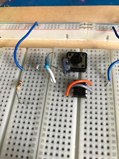
place the switch and the 555 timer on the board
 

Step two

connect pin 2 to pin 6 then connect pin 8 and 4

Step three

connect pin 8 to pin 6 with a 10k resistor 

Step four

connect pin 1 to pin 6 with a 10k resistor 

Step five

connect the capacitors negative lead to pin 1 of the 555 timer 

Step six

connect pin 3 to the positive lead of the capacitor with a 100k resistor
 

Step seven

connect one pin of the switch to the same row as the positive lead of the capacitor 

Step eight

connect pin 2 of the 555 a different pin on the switch 

Step Nine

connect the anode of the led to pin 3 of the 555 timer then connect the cathode to a resistor  that is then connected to the negative rail of the board 

Step Ten

connect pin 1 to the negative rail and pin 8 to the positive rail of the board now your circuit ready to test 


Fritzing layouts


Don't forget to check out the daily dobby on social media Facebook   Twitter 


Thanks for taking the time to read this if you liked what you've read then please check back tomorrow after 17.00bst for another update thanks again. Dobby 

Sunday, 30 July 2017

Project day #13 Audio Switch Board Build


Good afternoon folks and welcome to another Project day this weeks project is a Audio Switch Board build 

just a quick build for this weeks project day. I will be putting together an Audio Switch Board that I got from ebay 


Step one 

solder the 3.5mm jack to the circuit board 


Step two

solder the white connector on to the board 

Step three

now solder the blue connector to the board 


Step four

the last step is to solder the rca connector on to the board and test 


Don't forget to check out the daily dobby on social media Facebook   Twitter 

Thanks for taking the time to read this if you liked what you've read then please check back tomorrow after 17.00bst for another update thanks again. Dobby 

Saturday, 29 July 2017

The News #13


Good afternoon folks and welcome to this weeks news update where I talk about how my weeks gone and upcoming projects and other things.


The first piece of news I would like to share is an update on my 3d printer build the machine is now built I'm just waiting for a free parts that where missing from the box  there will be an post on it very soon .

I haven't had much time for other project this week but I have had a bit of time to work on a circuit for Monday which I think will be useful for future projects.

That's about it for this week ,


This weeks post 


Don't forget to check out the daily dobby on social media Facebook   Twitter 


Thanks for taking the time to read this if you liked what you've read then please check back tomorrow after 17.00bst for another update thanks again Dobby


Friday, 28 July 2017

Flashback Friday #13 Apple 2

Good afternoon folks and welcome to another Flashback Friday this weeks blast from the past is Apple 2


The Apple 2 is an 8-bit home computer, one of the first highly successful mass-produced microcomputer products, designed primarily by Steve Wozniak (Steve Jobs oversaw the development of the Apple II's foam-molded plastic case and Rod Holt developed the switching power supply). It was introduced in 1977 at the West Coast Computer Faire by Jobs and was the first consumer product sold by Apple Computer. It is the first model in a series of computers which were produced until Apple IIe production ceased in November 1993. The Apple II marks Apple's first launch of a personal computer aimed at a consumer market – branded towards American households rather than businessmen or computer hobbyists.
Along with the PET 2001 and the TRS-80, Byte magazine referred to these as the "1977 Trinity" of personal computing.The Apple II had the defining feature of being able to display color graphics, and this capability was the reason why the Apple logo was redesigned to have a spectrum of colors.

History

By 1976, Steve Jobs had convinced the product designer Jerry Manock (who had formerly worked at Hewlett Packard designing calculators) to create the "shell" for the Apple II – a smooth case inspired by kitchen appliances that would conceal the internal mechanics The earliest Apple IIs were assembled in Silicon Valley, and later in Texas; printed circuit boards were manufactured in Ireland and Singapore. The first computers went on sale on June 10, 1977[with a MOS Technology 6502 microprocessor running at 1.023 MHz, two game paddles (no longer bundled as of 1980 because they violated FCC regulations), 4 kB of RAM, an audio cassette interface for loading programs and storing data, and the Integer BASIC programming language built into the ROMs. The video controller displays 24 lines by 40 columns of monochrome, upper-case-only (the original character set matches ASCII characters 20h to 5Fh) text on the screen, with NTSC composite video output suitable for display on a TV monitor, or on a regular TV set by way of a separate RF modulator. The original retail price of the computer was $1,298 (with 4 kB of RAM) and $2,638 (with the maximum 48 kB of RAM). To reflect the computer's color graphics capability, the Apple logo on the casing has rainbow stripes,which remained a part of Apple's corporate logo until early 1998. Perhaps most significantly, the Apple II was a catalyst for personal computers across many industries; responsible for opening the doors to software marketed at consumers.


My experience 

I have never used one of these but would love to get the chance 


Don't forget to check out the daily dobby on social media Facebook   Twitter 


Thanks for taking the time to read this if you liked what you've read then please check back tomorrow after 17.00bst for another update thanks again. Dobby 


Thursday, 27 July 2017

Toolbox Thursday #13 30W soldering

Good afternoon folks and welcome to another Toolbox Thursday this weeks tool is a 30w soldering that I got from bang good 


How my toolbox Thursday reviews work the first thing I will talk about is what its like to setup  then I will move on what its like to use and to where you can get one from (there may be an affiliate link if you would like to help me out ) and if its good value for money and the last thing in the review will be my overall rating of the item it will be a 5 star system with 1 being the lowest and 5 being the highest .


Setup 

the setup was very simple with this iron is very easy to tin 


Use 

I picked this this iron mainly for the price it was which is very cheap after using this iron for a few hours I found it very comfortable to use . The iron heats up to a very reasonable temperature of around 400c very quickly. The tip takes solder and was very easy to keep tinned. the iron preformed very well on fairly heavy gauge wire and worked great on pcb with through hole components


Where can you get one 

you can get one of these from bang good by clicking here

Rating 

overall I pleased with this iron given its price under £5 you can't really go wrong I am going to it 4 stars out of 5 


Don't forget to check out the daily dobby on social media Facebook   Twitter 


Thanks for taking the time to read this if you liked what you've read then please check back tomorrow after 17.00BST for another update thanks again. Dobby 


Wednesday, 26 July 2017

Postbox #13

Good afternoon folks and welcome to another post box this I have 3 items to show you let's get started.


Item one 

first up this week is 10 EL817 Optocouplers  that I got to have a play with and see what I make
with them stay tuned to see what I make  


Item two 

the next item is a 60w soldering I that I got to test a out and use for an upcoming project that will be announced soon


Item three 

the last item in this very short postbox is a Geekcreit® K150 ICSP USB PIC Microcontroller Programmer which I picked up to try out on a friends recommendation I will be doing a review in an upcoming Toolbox Thursday 


Don't forget to check out the daily dobby on social media Facebook   Twitter 


Thanks for taking the time to read this if you liked what you've read then please check back tomorrow after 17.00bst for another update thanks again. Dobby 


Tuesday, 25 July 2017

Training Tuesday #13 Breadboarding basics

Good afternoon folks welcome to another Training Tuesday this week we will cover Breadboarding basics 


Tools or items needed 

a breadboard and some component's
 
The purpose of the breadboard is to make quick electrical connections between components- like resistors, LEDs, capacitors, etc- so that you can test your circuit before permanently soldering it together.  Breadboards have many small sockets on them, and some groups of sockets are electrically connected to each other.  On the underside of the board there are many small metal strips which physically connect certain groups of sockets together and allow electricity to flow freely between them.  These strips are probably not visible on the underside of your breadboard, but the third picture shows how they are organized.

Breadboards are usually divided into four sections, two outer sections and two inner sections.  Each row of five sockets in the inner sections are electrically connected to each other .  The two outer sections of the breadboard are usually used exclusively for power.  On many breadboards these sockets will be labeled with colors denoting positive voltage (usually red) and ground (black or blue).  It is important to note that on many breadboards the power lines only run half the length of the board .  You will need to run a wire between these two sections to send power to from one end to the other.  There is nothing special about the outer sections of the breadboard that makes particularly suitable for power other than that they run most of  the length of the board, but if you choose to use these rows for other things you may confuse others or even yourself, so it is good practice to use these for power only.

The first thing to do is send power to the breadboard.  Breadboards do not have their own power supply.  Some breadboards come with a power supply attached, but it is usually not connected directly to the power lines on the breadboard.
Power supplies come in many shapes and sizes, you may have to dial in the voltage or your power supply may only let you chose from one or a few types voltage levels.  For this tutorial (and for many of your future projects) we will be using 5V DC power.  This means that you will make two connections to your power supply, +5 and ground.

Alternative power supplies:
-use the +5 volt and GND (ground) pins of an arduino (you must plug the arduino into a computer or wall socket via usb first)
-battery- will require an attachment to connect to your breadboard


Now the breadboard is powered.  Convince yourself by using a multimeter to measure the voltage of any of the sockets in the power lines of the board.


What have we learned 

we have covered the very basics of breadboarding  


Don't forget to check out the daily dobby on social media Facebook   Twitter 


Thanks for taking the time to read this if you liked what you've read then please check back tomorrow after 17.00bst for another update thanks again. Dobby 

Monday, 24 July 2017

Circuit Monday #13 push button switch

Good afternoon folks and welcome to another Circuit Monday todays circuit is Push button switch 

Components needed 

one push button switch 
one led
one resistor 

all my Circuits are breadboarded on the prototype board I made here 


Uses for this circuit 

this is a simple push button switch that lets power flow as long as you hold the button down so it could be used as a basic dead switch 


Step one 

place the button into the board 

Step two

connect pin one of the switch to the positive rail of the board 

Step three

connect the resistor to pin 3 of the switch 

Step four

connect the anode of led to the resisitor then connect the cathode to the negative rail of the board 


Step five

time to test the circuit 


Firtzing Layout 


Don't forget to check out the daily dobby on social media Facebook   Twitter 


Thanks for taking the time to read this if you liked what you've read then please check back tomorrow after 17.00bst for another update thanks again. Dobby /

Sunday, 23 July 2017

Project day #12 flexible light


Good afternoon folks and welcome to another Project day this weeks project is a flexible light 


Why I made this project 

I made this project to give a small flexible light that I could use in tight spaces and with my helping hand project that I made in Project day #6 also because I wanted to use up a car head light blub 


Parts Needed

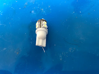
  1. a led car head light blub 
  2. a switch 
  3. a 12v battery holder and battery 
  4. a flexible coolant pipe 
  5. a project box


Step one 

To start is to dismantle the car head light this is done my straitening the leads out and twisting the plastic cover at the bottom of it


Step two

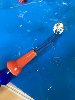
Now solder two lengths of wire onto the led bulb and then feed the wire into the coolant pipe


Step three

It's now time to drill two holes into to the top plate of the project box one for the coolant pipe (12mm) and another for the switch (6mm)

Step four

Fit the switch and coolant pipe into the top plate

Step five

solder the wire coming from the positive lead of the led to the switch 

Step six

solder the positive lead of the battery pack to the switch 

Step seven

Join the negative wires of the led and battery pack together

Step eight

Connect the top plate to the bottom and the project is finished 


How I could make this better  

I'd like to make this bigger with a few more lights and make it powered from the mains as well as the battery .


Don't forget to check out the daily dobby on social media Facebook   Twitter 

Thanks for taking the time to read this if you liked what you've read then please check back tomorrow after 17.00bst for another update thanks again. Dobby 
dobby repairs

Hi everyone I know that I haven't posted on here for quite some time  I probably won't be posting on here again for a while but I wa...

Total Pageviews