Showing posts with label tech. Show all posts

Sunday, 18 June 2017

Project Day #7 Bench Power Supply

Good afternoon folks and welcome to another Project day this weeks project is the bench power supply 


Why I made this project 

I make this power supply to solve my problem of not having the right voltages for testing and this does that. I have the following voltages on the power supply 3.3, 5 and 12 plus an adjustable voltage supply that can supply from 1 to 38 volts which will come in very handy in the future. 


Parts Needed

  • a pc power supply (I used an old one that I removed from a old pc )
  • 4 4mm binding post
  • a buck/boost power converter 
  • 2 leds I used a red and a green one 
  • 2 100k resistors 
  • a dummy load resistor
  • 4 ring connectors 
  • 4 nylon spacers
  • a usb jack (I used one that I removed from a pc )

I used heat shrink on all of the connections 


Step one 

The first step is to open a the power supply up this is normally only a few screws ( make sure it is not plugged into the mains )

Step two

the next step is to cut and  group the wires together by colour you should have 4 bundles(red 5v, orange 3.3nv , yellow 12v and black ground )plus 3 coloured wires (purple standby , brown 3.3 sense and green power on ) there may be a few other wires left over which I just cut and wrapped in electrical tape just so the couldn't short out.  

Step three

the next step is the join the brown wire to an orange wire this is a very important step is these wires are not connected the power supply will not work .

Step four

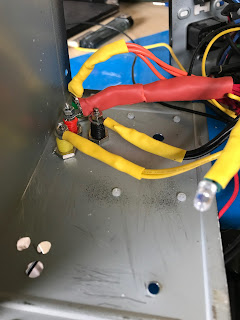
the fourth step is to solder a 100k resistor to the purple wire and a orange wire then solder those wires to the anode of two leds (I used red for the standby purple wire and green for the orange wire which is the power on indicator) then I soldered a black wire to the cathode of each led 


Step five

the next step is to solder the green and a black wire to the switch 

Step six

the next step is to drill holes in the case for the switch , the two leds, the usb jack  and four binding post  as well five  holes for the power converter spacers  and  attach them to it 


Step seven

the next step is to cut the wire bundles to a good length then twist and tin the ends of each bundle then attach a ring connector to each of the wire bundles then attach them to the binding post and also fit the switch and leds into place .


Step eight

the next step is to feed a yellow and black wire out to the back of the power supply then another pair of the same colours out of the hole for the power convertor and  red and black wire for the usb jack in the front the put the power supply back together .


Step Nine

next up is soldering the two wires at the back of the power supply to the dummy load resistor.


Step Ten

the tenth step is to connect the yellow and black wire to the power convertor and attach it to the front 

Step eleven

the last step is to solder the red and black wires to the red and black wires on the usb jack (I taped this up afterwards ) 


How I could make this better  

I think the main things I would change is the spacing on the binding post and possibly use a different power converter but apart from that I think this is a pretty good build and I am very pleased with it.


Thanks for taking the time to read this if you liked what you've read then please check back tomorrow after 17.00bst for another update thanks again. Dobby 


Thursday, 15 June 2017

Toolbox Thursday # 7 Dremel 3000

Good afternoon folks and welcome to another Toolbox Thursday this weeks tool is Dremel 3000


How my toolbox Thursday reviews work the first thing I will talk about is what its like to setup  then I will move on what its like to use and to where you can get one from (there may be an affiliate link if you would like to help me out ) and if its good value for money and the last thing in the review will be my overall rating of the item it will be a 5 star system with 1 being the lowest and 5 being the highest .


Setup 

this is a very easy tool to setup simply plug it into the mains and choose the bit you would like to use and fit it into the chuck 


Use 

this model has a very handy quick change feature for the bits which I use all of the time . due to it versatile nature I find myself using in a number of ways which include cutting, sanding and drilling it has a great feel in the hand which aids in its use. the adjustable speed is the main feature I like about this tool which helps make controlled cuts in fragile materials there is also a wide range of bits available to buy and use with this machine . my one came with a number of bits as well a really nice case that is very high quality. 


Where can you get one 

there are a number of places you can pick one of these up from and I would recommend shopping around but what ever price you pay it is great value for money 


Rating 

This is a fantastic tool that I can not recommend enough it works perfectly ever time my rating for it is a full 5 stars. 


Thanks for taking the time to read this if you liked what you've read then please check back tomorrow after 17.00BST for another update thanks again. Dobby 


Sunday, 4 June 2017

Project Day #5 Solder fume extractor

Good afternoon folks and welcome to another Project day this weeks project is the solder fume extractor 


Why I made this project 

I made this to help deal with the fume that come from solder which I find can make my eyes sore after a long build. the main part to this was two pc fans that I got from a old computer. so it was a pretty cheap build using things I had to hand the only item that I needed to order was the active carbon filter which I got from ebay but you can pick them up from garden centres and diy stores. by fitting the half a hose pipe joiner to the I can also vent the filtered fumes outside and well away from the work area thus making my soldering cleaner and more enjoyable .

Parts Needed 

2 12v pc fans
1 active carbon filter
1 red led
1 100k resistor
1 2.1mm female power jack
1 12v power supply
6 pieces of wood cut to fit around the fans
1 hose pipe joiner
1 switch


 Step one

the first this to do is to glue the pieces of wood together leaving the biggest parts for  the front and back unglued

Step two

on to the next step now which is to cut the hose pipe joiner in half as you can see in the picture   I used my dremel for this you want to cut so that there is a lip left on it .


Step three

the next step is the drill a hole big enough to fit the front end of the hose pipe joiner through and then glue it into place 


Step four

the forth step is the drill the mounting for the fans into both the front and back pieces to make sure these where in line on both pieces I marked the front and drilled through both pieces at once then I drilled holes in the front  for the led and switch as well as a big hole for the fans to suck the fumes in and one more in the back for the power jack.

Step five

the next step is to add 4 bolts through the holes join both fans together  and cut the filter to size to fit between the fans .

Step six

now on to the wiring I started by soldering a wire to the positive and negative pins of the power jack using a red wire for positive and a black wire for negative .

Step seven

then I soldered positive wire to the first pin on the switch and then I soldered positive wires from the fans and the 100k resistor to the second pin on the switch the I attached the resistor to the anode of the led 

Step eight

next join all three of the negative wires together and solder them to the cathode of the led 
that finishes of the wiring for this project

Step Nine

the next step is to bolt the fan to the back panel and place through the square that was made in step one .


Step Ten

the last step is to put the switch and led into place and bolt the front on I found one of the grills from the pc case and used that on the front to make it look a bit nicer 


How I could make this better  

there are not to many improvements I would make to this but if I had the chance I would use bigger fans and make the case bigger .

Thanks for taking the time to read this if you liked what you've read then please check back tomorrow after 17.00gmt for another update thanks again. Dobby 

Wednesday, 31 May 2017

post box # 5

Good afternoon and welcome to another post box this I have 7 items to show you let's get started 

Item one 

the first item this week is a set of ten flashing circuit  this is a basic solder training circuit they are good to practice on I got them to teach people how to solder.

Item two 

the second item is 50 BC37 pnp  transistors I picked these up to play around with and to replace a few in some repair work I have to do .

Item three 

the next item on this week is six banana connecter plugs I picked these up to use with the bench power supply which I should hopefully have ready to share in a future project day .

Item four 

this item is a bit of a strange one it is an attiny dev board and to be I haven't had much of a chance to look at how it works did come with an attiny 85 as well I will keep you updated with it and how I get on .

Item five 

next up is a bulk load of resistors that were only 99p so I grabbed them I'm always using resistors so it was a good buy.

Item six 

the sixth item today is two rolls of solder wick I picked these up to replace the one that had ran out and also because I am planning a post about desoldering very soon.

Item seven 

the last item in this weeks post box is a box of jumper wires I got these to you use with the prototyping board I made in Project day #3 and these are better than the ones I was using .

hope you enjoyed this week post box check back tomorrow for Toolbox Thursday 

Dobby 


Tuesday, 30 May 2017

Training Tuesday # 5 how to solder surface mount components

Welcome to another Training Tuesday this week will talk about surface mount components
Surface mount components can be very hard to solder so I hope this will help

Useful tools 

1. x1 soldering iron
2. PCB(Printed Circuit Board) with available pads
3. SMD (Surface Mount Device) component that matches the available pad
4. Solder (recommend water soluble, rosin core acceptable)
5. Desoldering braid
6. Flux w/ applicator
7. Tweezers
8. Rubbing alcohol (rosin core solder) OR
9. Water (for water soluble solder)
10. Anti-static cloth

Step one 

1. Check to be sure the pad size of the PCB lines up with the pins on the SMD

2. Clean the PCB of any dust or debris.

3. Turn the soldering iron on now, and set the temperature between 600-700 degrees.

Warning: When heated to these temperatures, you will be burned if you touch the tip of the soldering iron.

Step two


Align the pins of the component with the pads on the circuit board using tweezers. Since most surface mount components have the same amount of pins on both sides, it is important to find "pin 1" every time you place a new component.

Step three

1. Keep one hand still, holding the component in place with the tweezers.

2. By now, the soldering iron should be hot. Get a small to medium sized dot of solder on the tip.

3. Pick any corner pin on the component

4 . Touch and hold the soldering iron to the pad that will be associated with that pin.

5. If you have done this correctly, the solder should have transferred from the pad on the circuit board to the component pin, it does not matter if you have connected excess pins, this will be fixed later.

Step four 

There are 2 purposes for flux in soldering: to prevent beading of the solder, and help the solder flow from the soldering iron to the circuit board. Flux will be used on this board to limit the amount of bridged connections made, and generally make the job easier.

1. This substance is messy, so be sure to use an applicator. (toothpick, brush, etc.) In this case, I have used a metal tip.

2. Get a large amount of flux on the applicator.

3. Spread the flux over the pins on the opposite side of the component that was tacked down in the previous step.

Step five

1. Pick up the soldering iron in one hand, and the solder in the other,

2. Use the soldering iron to heat up the pad, not the pin on the component.

3. While the pin is hot, position the solder between the pad and the pin. The heat will melt the solder, and the flux will cause it to flow where it needs to.

4. Repeat this as many times as necessary.

Step six

It is fairly common that while preforming the previous step, a solder bridge will develop. A solder bridge might look something like the picture below.

These steps will also work for removing the component from the board.

1. Take the desoldering wick and place it over the solder you want to remove.

2. With the soldering iron, lightly press on the wick, to ensure the heat is transferred through to the solder.

Warning: Remember that heat removes solder, not pressure. Too much pressure applied could remove the pad or pin on the component, ruining the component or board.

Step seven

If water soluble solder was used, replace rubbing alcohol with water.

1. Take the anti-static cloth and pour a small amount of rubbing alcohol onto it.

2. Gently clean around the newly soldered component, and where any excess flux exists. This will give a more professional look.
I hope you have found this helpful there is also a way to use hot air that I will be sharing soon
Dobby

Sunday, 28 May 2017

Project Day # 4 Bottle light

Hi guys and girls welcome another Project day this week due to the fact it is a bank holiday here in the U.K I thought I make a bottle light out of an empty beer bottle from a BBQ that I had yesterday evening. I feel I should say I have to make one little change to this I did have a 10k on the circuit but after completing it I found that it wasn't working so I had to remove it .

Parts needed 

1 switch 
2 leds
1 bottle
1 5v power supply 
1 100k resistor
2 pieces of wood one big enough to fit the bottle on and one to go inside the bottle 
Wire


step one 

Drink a bottle of beer or glass bottled drink of choice I drank a Coors light so that's what I will be using in this project I then used a Dremel  to make a hole I the bottom of the bottle (use a low speed on the Dremel and  wear safety glasses)

 Step two 

I soldered the cathode of the first led to the anode of the second 

Step three 

I soldered a wire to one pin on the switch and heat shrank it 

Step four

I then soldered the 100k resistor to the wire coming from the switch 

Step Five

I then soldered the resistor with a wire to the anode of the led pair 

Step six 

I then soldered a wire from the cathode side of the led pair to the - side of the power supply.

Step seven 

I then soldered the + side of the power supply onto the switch  and that's the wiring competed 

Step eight 

I drilled a hole in the bigger piece of wood and fitted the small piece into it I held it with super glue.


Step nine

I taped the led to the top of the small piece of wood and glue the switch in place 


Step ten 

I placed the bottle over the top and that's the project finished it's not very bright in the daylight I post a picture of it in the dark on my twitter later on today .

improvements 

I think the first improvement I would  make is to paint the base then Id find a more powerful led to go in it also I would like to fit a pot so I can dim the light but I am going to use it on my bed bedside table . 

hope you enjoyed this project
Dobby 


dobby repairs

Hi everyone I know that I haven't posted on here for quite some time  I probably won't be posting on here again for a while but I wa...

Total Pageviews