Showing posts with label electronics. Show all posts

Monday, 31 July 2017

Circuit Monday #14 Latching switch

Good afternoon folks and welcome to another Circuit Monday todays circuit is A latching switch 

Components needed 

1 LED 
1555 TIMER 
1PUSH BUTTON SWITCH 
1CAPACTIOR 
4 RESISTORS 

all my Circuits are breadboarded on the prototype board I made here 


Uses for this circuit 

you can use this circuit for turning on and off power to all sorts of things 
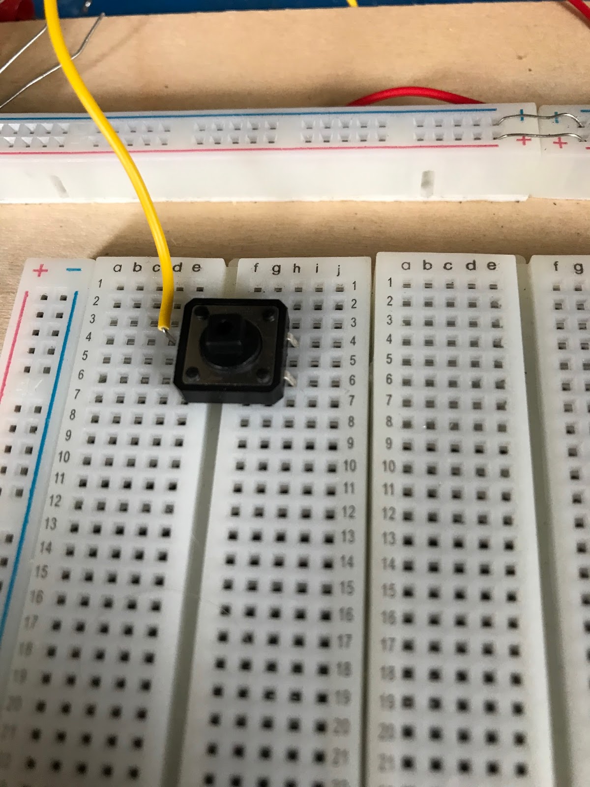


Step one

place the switch and the 555 timer on the board
 

Step two

connect pin 2 to pin 6 then connect pin 8 and 4

Step three

connect pin 8 to pin 6 with a 10k resistor 

Step four

connect pin 1 to pin 6 with a 10k resistor 

Step five

connect the capacitors negative lead to pin 1 of the 555 timer 

Step six

connect pin 3 to the positive lead of the capacitor with a 100k resistor
 

Step seven

connect one pin of the switch to the same row as the positive lead of the capacitor 

Step eight

connect pin 2 of the 555 a different pin on the switch 

Step Nine

connect the anode of the led to pin 3 of the 555 timer then connect the cathode to a resistor  that is then connected to the negative rail of the board 

Step Ten

connect pin 1 to the negative rail and pin 8 to the positive rail of the board now your circuit ready to test 


Fritzing layouts


Don't forget to check out the daily dobby on social media Facebook   Twitter 


Thanks for taking the time to read this if you liked what you've read then please check back tomorrow after 17.00bst for another update thanks again. Dobby 

Monday, 24 July 2017

Circuit Monday #13 push button switch

Good afternoon folks and welcome to another Circuit Monday todays circuit is Push button switch 

Components needed 

one push button switch 
one led
one resistor 

all my Circuits are breadboarded on the prototype board I made here 


Uses for this circuit 

this is a simple push button switch that lets power flow as long as you hold the button down so it could be used as a basic dead switch 


Step one 

place the button into the board 

Step two

connect pin one of the switch to the positive rail of the board 

Step three

connect the resistor to pin 3 of the switch 

Step four

connect the anode of led to the resisitor then connect the cathode to the negative rail of the board 


Step five

time to test the circuit 


Firtzing Layout 


Don't forget to check out the daily dobby on social media Facebook   Twitter 


Thanks for taking the time to read this if you liked what you've read then please check back tomorrow after 17.00bst for another update thanks again. Dobby /

Monday, 17 July 2017

Circuit Monday #12 IR Tester

Good afternoon folks and welcome to another Circuit Monday todays circuit is a IR tester

Components needed 

1 IR sensor
A 1k resistor 
1 red led 
jumper wires 

all my Circuits are breadboarded on the prototype board I made here 


Uses for this circuit

you can use circuit to test remotes and other I R emitting devices


Step one 

place the IR sensor into the board

Step two

place the led into the board 

Step three

connect the cathode of the led (the shortest lead) to the middle pin of the IR sensor 

Step four

Connect the anode of the led (the longest lead) to the left hand pin of the IR sensor with a jumper wire.

Step Five

connect a jumper wire between the middle pin of the IR sensor and the negative rail of the board 

Step six

Connect a Jumper wire between the right hand pin of the IR sensor and the Positive rail of the board and test your circuit 


I powered this circuit with 3.3 volts from my bench power supply I made here .when you press a button on a remote the led should flicker you and also run this circuit with a buzzer .


Don't forget to check out the daily dobby on social media Facebook   Twitter 


Thanks for taking the time to read this if you liked what you've read then please check back tomorrow after 17.00bst for another update thanks again. Dobby

Sunday, 16 July 2017

Project day #11 Shed light

Good afternoon folks and welcome to another Project day this weeks project is the a light for my shed 


Why I made this project 

I made this  so that I could use the shed at night or in the gloomy British weather . 


Parts Needed

1 block connector 
1 light switch and back plate
a length  of cable with a mains plug
one light fitting 


Setting up the light fitting 

I was using a premade light that needed a bit of assembly this was just a case of pushing the lighting fins into the main body 


Step one 

Drill holes into the back place for the cable and fixings

Step two

attach your back plate to the surface you wish to mount it to using screws (I attached mine to my desk ) and then feed your cable into the back plate 


Step three

next wire your switch according to local standards   and attach it to the back plate 

for the UK is as follows 


Step four

The next step is  to is join your light fitting to you power cable using the block connector 

Step five

the last step is to mount you light  where you would like it and test it out 


How I could make this better  

id would like to change the light for a better one but apart from that I think this will help me work later into the night 


Don't forget to check out the daily dobby on social media Facebook   Twitter 

Thanks for taking the time to read this if you liked what you've read then please check back tomorrow after 17.00bst for another update thanks again. Dobby 

Monday, 10 July 2017

Circuit Monday #11 Ajustable Power supply

Good afternoon folks and welcome to another Circuit Monday todays circuit is Ajustable Power supply

Components needed 

all my Circuits are breadboarded on the prototype board I made here 

  1. LM317 voltage regulator
  2. 100k potentiometer
  3. a resistor that will give you the output voltage you would like if this case id like 9volts so I am using a 100 ohms resistor 


Uses for this circuit 

sometimes we can't find the right voltage power supply for our projects or project need more that one voltage to run using this three component circuit can handle many different task


Step one 

Place the LM317T into the board 


Step two

The next step is to place the potentiometer to board leaving a bigger gap than I did 

Step three

the third step is to attach your ground to one of the out side pins of your potentiometer

Step four

The next is to connect your resistor to the middle pin of your potentiometer and the adjust pin on the LM317 (please see pinout )

Step five

the final step is to attach your power source (12v in this case ) to the V in pin of the LM317 


Testing 

now the circuit is finished you can test  with a multimeter  by connecting it to the V out and the ground 


Fritzing layouts 


Don't forget to check out the daily dobby on social media Facebook   Twitter 


Thanks for taking the time to read this if you liked what you've read then please check back tomorrow after 17.00bst for another update thanks again. Dobby 

dobby repairs

Hi everyone I know that I haven't posted on here for quite some time  I probably won't be posting on here again for a while but I wa...

Total Pageviews