
Saturday, 30 September 2017

Friday, 29 September 2017
Voltage drop
Voltage drop describes how energy is supplied of a voltage source that is reduced as electric current moves through the passive elements (elements that do not supply voltage) of an electrical circuit. Voltage drops across internal resistances of the source, across conductors, across contacts, and across connectors are undesired as the supplied energy is lost (dissipated). Voltage drops across loads and across other active circuit elements are desired as the supplied energy performs useful work.
For example, an electric space heater may have a resistance of ten ohms, and the wires which supply it may have a resistance of 0.2 ohms, about 2% of the total circuit resistance. This means that approximately 2% of the supplied voltage is lost in the wire itself. Excessive voltage drop may result in unsatisfactory operation of, and damage to, electrical and electronic equipment.
National and local electrical codes may set guidelines for the maximum voltage drop allowed in electrical wiring, to ensure efficiency of distribution and proper operation of electrical equipment. The maximum permitted voltage drop varies from one country to another.n electronic design and power transmission, various techniques are employed to compensate for the effect of voltage drop on long circuits or where voltage levels must be accurately maintained. The simplest way to reduce voltage drop is to increase the diameter of the conductor between the source and the load, which lowers the overall resistance. In power distribution systems, a given amount of power can be transmitted with less voltage drop if a higher voltage is used. More sophisticated techniques use active elements to compensate for the undesired voltage drop.
If the voltage between the DC source and the first resistor (67 ohms) is measured, the voltage potential at the first resistor will be slightly less than nine volts. The current passes through the conductor (wire) from the DC source to the first resistor; as this occurs, some of the supplied energy is "lost" (unavailable to the load), due to the resistance of the conductor. Voltage drop exists in both the supply and return wires of a circuit. If the voltage across each resistor is measured, the measurement will be a significant number. That represents the energy used by the resistor. The larger the resistor, the more energy used by that resistor, and the bigger the voltage drop across that resistor.
Ohm's Law can be used to verify voltage drop. In a DC circuit, voltage equals current multiplied by resistance. . Also, Kirchhoff's circuit laws state that in any DC circuit, the sum of the voltage drops across each component of the circuit is equal to the supply voltage.
Electrical impedance is commonly represented by the variable Z and measured in ohms at a specific frequency. Electrical impedance is computed as the vector sum of electrical resistance, capacitive reactance, and inductive reactance.
The amount of impedance in an alternating-current circuit depends on the frequency of the alternating current and the magnetic permeability of electrical conductors and electrically isolated elements (including surrounding elements), which varies with their size and spacing.
Analogous to Ohm's law for direct-current circuits, electrical impedance may be expressed by the formula . So, the voltage drop in an AC circuit is the product of the current and the impedance of the circuit.
For example, an electric space heater may have a resistance of ten ohms, and the wires which supply it may have a resistance of 0.2 ohms, about 2% of the total circuit resistance. This means that approximately 2% of the supplied voltage is lost in the wire itself. Excessive voltage drop may result in unsatisfactory operation of, and damage to, electrical and electronic equipment.
National and local electrical codes may set guidelines for the maximum voltage drop allowed in electrical wiring, to ensure efficiency of distribution and proper operation of electrical equipment. The maximum permitted voltage drop varies from one country to another.n electronic design and power transmission, various techniques are employed to compensate for the effect of voltage drop on long circuits or where voltage levels must be accurately maintained. The simplest way to reduce voltage drop is to increase the diameter of the conductor between the source and the load, which lowers the overall resistance. In power distribution systems, a given amount of power can be transmitted with less voltage drop if a higher voltage is used. More sophisticated techniques use active elements to compensate for the undesired voltage drop.
Voltage drop in direct-current circuits: resistance
Consider a direct-current circuit with a nine-volt DC source; three resistors of 67 ohms, 100 ohms, and 470 ohms; and a light bulb—all connected in series. The DC source, the conductors (wires), the resistors, and the light bulb (the load) all have resistance; all use and dissipate supplied energy to some degree. Their physical characteristics determine how much energy. For example, the DC resistance of a conductor depends upon the conductor's length, cross-sectional area, type of material, and temperature.If the voltage between the DC source and the first resistor (67 ohms) is measured, the voltage potential at the first resistor will be slightly less than nine volts. The current passes through the conductor (wire) from the DC source to the first resistor; as this occurs, some of the supplied energy is "lost" (unavailable to the load), due to the resistance of the conductor. Voltage drop exists in both the supply and return wires of a circuit. If the voltage across each resistor is measured, the measurement will be a significant number. That represents the energy used by the resistor. The larger the resistor, the more energy used by that resistor, and the bigger the voltage drop across that resistor.
Ohm's Law can be used to verify voltage drop. In a DC circuit, voltage equals current multiplied by resistance. . Also, Kirchhoff's circuit laws state that in any DC circuit, the sum of the voltage drops across each component of the circuit is equal to the supply voltage.

Voltage drop in alternating-current circuits: impedance
In alternating-current circuits, opposition to current flow occurs because of resistance, just as in direct-current circuits. However, alternating current circuits also include a second kind of opposition to current flow: reactance. The sum of oppositions to current flow from both resistance and reactance is called impedance.Electrical impedance is commonly represented by the variable Z and measured in ohms at a specific frequency. Electrical impedance is computed as the vector sum of electrical resistance, capacitive reactance, and inductive reactance.
The amount of impedance in an alternating-current circuit depends on the frequency of the alternating current and the magnetic permeability of electrical conductors and electrically isolated elements (including surrounding elements), which varies with their size and spacing.
Analogous to Ohm's law for direct-current circuits, electrical impedance may be expressed by the formula . So, the voltage drop in an AC circuit is the product of the current and the impedance of the circuit.

Thursday, 28 September 2017
PC test bench Plans
hi and welcome to a quick post showing off my pc test bench plans that I am planning to build in an upcoming project day the main uses for this will be testing different hardware configurations without putting them into case this is only a basic drawing with a lot more details in the build post
 the main parts of this project is the motherboard mounting which is on the top of the bench which will have different mounting holes for different types of boards as wellas a hard drive mounting board that will include some usb ports and testing leds
dobby

dobby
Wednesday, 27 September 2017
Low-frequency oscillation
Low-frequency oscillation (LFO) is an electronic signal which is usually below 20 Hz and creates a rhythmic pulse or sweep. This pulse or sweep is often used to modulate synthesizers, delay lines and other audio equipment in order to create effects used in the production of electronic music. Audio effects such as vibrato, tremolo and phasing are examples. The abbreviation LFO is also very often used to refer to low-frequency oscillators themselves.
Using a low-frequency oscillation signal as a means of modulating another signal introduces complexities into the resulting sound, such that a variety of effects can be achieved. The specifics vary greatly depending on the type of modulation, the relative frequencies of the LFO signal and the signal being modulated, et cetera.
History
Low-frequency oscillation as a concept was first introduced in the modular synths of the 1960s and 70s. Often the LFO effect was accidental, so there were myriad configurations that could be 'patched' by the synth operator. LFOs have since appeared in some form on almost every synthesizer. More recently other electronic musical instruments, such as samplers and software synthesizers, have included LFOs to increase their sound alteration capabilities.Overview
The primary oscillator circuits of a synthesizer are used to create the audio signals. A LFO is a secondary oscillator that operates at a significantly lower frequency (hence its name), typically below 20 Hz. This lower frequency or control signal is used to modulate another component's value, changing the sound without introducing another source. Like a standard oscillator, this usually takes the form of a periodic waveform, such as a sine, sawtooth, triangle or square wave. Also like a standard oscillator, LFOs can incorporate any number of waveform types, including user-defined wavetables, rectified waves and random signals.Using a low-frequency oscillation signal as a means of modulating another signal introduces complexities into the resulting sound, such that a variety of effects can be achieved. The specifics vary greatly depending on the type of modulation, the relative frequencies of the LFO signal and the signal being modulated, et cetera.
Tuesday, 26 September 2017
Breadboards
A breadboard is a construction base for prototyping of electronics. Originally it was literally a bread board, a polished piece of wood used for slicing bread. In the 1970s the solderless breadboard (AKA plugboard, a terminal array board) became available and nowadays the term "breadboard" is commonly used to refer to these.
Because the solderless breadboard does not require soldering, it is reusable. This makes it easy to use for creating temporary prototypes and experimenting with circuit design. For this reason, solderless breadboards are also extremely popular with students and in technological education. Older breadboard types did not have this property. A stripboard (Veroboard) and similar prototyping printed circuit boards, which are used to build semi-permanent soldered prototypes or one-offs, cannot easily be reused. A variety of electronic systems may be prototyped by using breadboards, from small analog and digital circuits to complete central processing units (CPUs).
Breadboards have evolved over time, with the term now being used for all kinds of prototype electronic devices. For example, US Patent 3,145,483,was filed in 1961 and describes a wooden plate breadboard with mounted springs and other facilities. US Patent 3,496,419,was filed in 1967 and refers to a particular printed circuit board layout as a Printed Circuit Breadboard. Both examples refer to and describe other types of breadboards as prior art.
The breadboard most commonly used today is usually made of white plastic and is a pluggable (solderless) breadboard. It was designed by Ronald J. Portugal in 1971.
Modern circuit designs are generally developed using a schematic capture and simulation system, and tested in software simulation before the first prototype circuits are built on a printed circuit board. Integrated circuit designs are a more extreme version of the same process: since producing prototype silicon is costly, extensive software simulations are performed before fabricating the first prototypes. However, prototyping techniques are still used for some applications such as RF circuits, or where software models of components are inexact or incomplete.
You could also use a square grid of pairs of holes where one hole per pair connects to its row and the other connects to its column. This same shape can be in a circle with rows and columns each spiraling opposite clockwise/counterclockwise.
The spacing between the clips (lead pitch) is typically 0.1 in (2.54 mm). Integrated circuits (ICs) in dual in-line packages (DIPs) can be inserted to straddle the centerline of the block. Interconnecting wires and the leads of discrete components (such as capacitors, resistors, and inductors) can be inserted into the remaining free holes to complete the circuit. Where ICs are not used, discrete components and connecting wires may use any of the holes. Typically the spring clips are rated for 1 ampere at 5 volts and 0.333 amperes at 15 volts (5 watts). The edge of the board has male and female notches so boards can be clipped together to form a large breadboard.
In a more robust variant, one or more breadboard strips are mounted on a sheet of metal. Typically, that backing sheet also holds a number of binding posts. These posts provide a clean way to connect an external power supply. This type of breadboard may be slightly easier to handle. Several images in this article show such solderless breadboards.
Differently colored wires and color-coding discipline are often adhered to for consistency. However, the number of available colors is typically far fewer than the number of signal types or paths. Typically, a few wire colors are reserved for the supply voltages and ground (e.g., red, blue, black), some are reserved for main signals, and the rest are simply used where convenient. Some ready-to-use jump wire sets use the color to indicate the length of the wires, but these sets do not allow a meaningful color-coding schema.
Because the solderless breadboard does not require soldering, it is reusable. This makes it easy to use for creating temporary prototypes and experimenting with circuit design. For this reason, solderless breadboards are also extremely popular with students and in technological education. Older breadboard types did not have this property. A stripboard (Veroboard) and similar prototyping printed circuit boards, which are used to build semi-permanent soldered prototypes or one-offs, cannot easily be reused. A variety of electronic systems may be prototyped by using breadboards, from small analog and digital circuits to complete central processing units (CPUs).
Evolution
In the early days of radio, amateurs nailed bare copper wires or terminal strips to a wooden board (often literally a board to slice bread on) and soldered electronic components to them.Sometimes a paper schematic diagram was first glued to the board as a guide to placing terminals, then components and wires were installed over their symbols on the schematic. Using thumbtacks or small nails as mounting posts was also common.Breadboards have evolved over time, with the term now being used for all kinds of prototype electronic devices. For example, US Patent 3,145,483,was filed in 1961 and describes a wooden plate breadboard with mounted springs and other facilities. US Patent 3,496,419,was filed in 1967 and refers to a particular printed circuit board layout as a Printed Circuit Breadboard. Both examples refer to and describe other types of breadboards as prior art.
The breadboard most commonly used today is usually made of white plastic and is a pluggable (solderless) breadboard. It was designed by Ronald J. Portugal in 1971.
Alternatives
Alternative methods to create prototypes are point-to-point construction (reminiscent of the original wooden breadboards), wire wrap, wiring pencil, and boards like the stripboard. Complicated systems, such as modern computers comprising millions of transistors, diodes, and resistors, do not lend themselves to prototyping using breadboards, as their complex designs can be difficult to lay out and debug on a breadboard.Modern circuit designs are generally developed using a schematic capture and simulation system, and tested in software simulation before the first prototype circuits are built on a printed circuit board. Integrated circuit designs are a more extreme version of the same process: since producing prototype silicon is costly, extensive software simulations are performed before fabricating the first prototypes. However, prototyping techniques are still used for some applications such as RF circuits, or where software models of components are inexact or incomplete.
You could also use a square grid of pairs of holes where one hole per pair connects to its row and the other connects to its column. This same shape can be in a circle with rows and columns each spiraling opposite clockwise/counterclockwise.
Solderless breadboard
Typical specifications
A modern solderless breadboard socket consists of a perforated block of plastic with numerous tin plated phosphor bronze or nickel silver alloy spring clips under the perforations. The clips are often called tie points or contact points. The number of tie points is often given in the specification of the breadboard.The spacing between the clips (lead pitch) is typically 0.1 in (2.54 mm). Integrated circuits (ICs) in dual in-line packages (DIPs) can be inserted to straddle the centerline of the block. Interconnecting wires and the leads of discrete components (such as capacitors, resistors, and inductors) can be inserted into the remaining free holes to complete the circuit. Where ICs are not used, discrete components and connecting wires may use any of the holes. Typically the spring clips are rated for 1 ampere at 5 volts and 0.333 amperes at 15 volts (5 watts). The edge of the board has male and female notches so boards can be clipped together to form a large breadboard.
Bus and terminal strips
Solderless breadboards are available from several different manufacturers, but most share a similar layout. The layout of a typical solderless breadboard is made up from two types of areas, called strips. Strips consist of interconnected electrical terminals.- Terminal strips
- The main areas, to hold most of the electronic components.
- In the middle of a terminal strip of a breadboard, one typically finds a notch running in parallel to the long side. The notch is to mark the centerline of the terminal strip and provides limited airflow (cooling) to DIP ICs straddling the centerline. The clips on the right and left of the notch are each connected in a radial way; typically five clips (i.e., beneath five holes) in a row on each side of the notch are electrically connected. The five rows on the left of the notch are often marked as A, B, C, D, and E, while the ones on the right are marked F, G, H, I and J. When a "skinny" dual in-line pin package (DIP) integrated circuit (such as a typical DIP-14 or DIP-16, which have a 0.3-inch (7.6 mm) separation between the pin rows) is plugged into a breadboard, the pins of one side of the chip are supposed to go into row E while the pins of the other side go into row F on the other side of the notch. The columns are numbered 1 - 50 or whatever number of columns there are.
- Bus strips
- To provide power to the electronic components.
- A bus strip usually contains two rows: one for ground and one for a supply voltage. However, some breadboards only provide a single-row power distributions bus strip on each long side. Typically the row intended for a supply voltage is marked in red, while the row for ground is marked in blue or black. Some manufacturers connect all terminals in a column. Others just connect groups of, for example, 25 consecutive terminals in a column. The latter design provides a circuit designer with some more control over crosstalk (inductively coupled noise) on the power supply bus. Often the groups in a bus strip are indicated by gaps in the color marking.
- Bus strips typically run down one or both sides of a terminal strip or between terminal strips. On large breadboards additional bus strips can often be found on the top and bottom of terminal strips.
- Note there are two different common alignments for the power bus strips. On small boards, with about 30 rows, the holes for the power bus are often aligned between the signal holes. On larger boards, about 63 rows, the power bus strip holes are often in alignment with the signal holes. This makes some accessories designed for one board type incompatible with the other. For example, some Raspberry Pi GPIO to breadboard adapters use offset aligned power pins, making them not fit breadboards with aligned power bus rows. There are no official standards, so the users need to pay extra attention to the compatibility between a specific model of breadboard and a specific accessory. Vendors of accessories and breadboards are not always clear in their specifications of which alignment they use. Seeing a close up photograph of the pin/hole arrangement can help determine compatibility.
In a more robust variant, one or more breadboard strips are mounted on a sheet of metal. Typically, that backing sheet also holds a number of binding posts. These posts provide a clean way to connect an external power supply. This type of breadboard may be slightly easier to handle. Several images in this article show such solderless breadboards.
Diagram
A "full size" terminal breadboard strip typically consists of around 56 to 65 rows of connectors, each row containing the above-mentioned two sets of connected clips (A to E and F to J). Together with bus strips on each side this makes up a typical 784 to 910 tie point solderless breadboard. "Small size" strips typically come with around 30 rows. Miniature solderless breadboards as small as 17 rows (no bus strips, 170 tie points) can be found, but these are only suitable for small and simple designs.Jump wires
Jump wires (also called jumper wires) for solderless breadboarding can be obtained in ready-to-use jump wire sets or can be manually manufactured. The latter can become tedious work for larger circuits. Ready-to-use jump wires come in different qualities, some even with tiny plugs attached to the wire ends. Jump wire material for ready-made or homemade wires should usually be 22 AWG (0.33 mm2) solid copper, tin-plated wire - assuming no tiny plugs are to be attached to the wire ends. The wire ends should be stripped 3⁄16 to 5⁄16 in (4.8 to 7.9 mm). Shorter stripped wires might result in bad contact with the board's spring clips (insulation being caught in the springs). Longer stripped wires increase the likelihood of short-circuits on the board. Needle-nose pliers and tweezers are helpful when inserting or removing wires, particularly on crowded boards.Differently colored wires and color-coding discipline are often adhered to for consistency. However, the number of available colors is typically far fewer than the number of signal types or paths. Typically, a few wire colors are reserved for the supply voltages and ground (e.g., red, blue, black), some are reserved for main signals, and the rest are simply used where convenient. Some ready-to-use jump wire sets use the color to indicate the length of the wires, but these sets do not allow a meaningful color-coding schema.
Monday, 25 September 2017
high-pass filter
A high-pass filter (HPF) is an electronic filter that passes signals with a frequency higher than a certain cutoff frequency and attenuates signals with frequencies lower than the cutoff frequency. The amount of attenuation for each frequency depends on the filter design. A high-pass filter is usually modeled as a linear time-invariant system. It is sometimes called a low-cut filter or bass-cut filter. High-pass filters have many uses, such as blocking DC from circuitry sensitive to non-zero average voltages or radio frequency devices. They can also be used in conjunction with a low-pass filter to produce a bandpass filter.
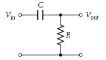 The simple first-order electronic high-pass filter shown in Figure 1 is implemented by placing an input voltage across the series combination of a capacitor and a resistor and using the voltage across the resistor as an output. The product of the resistance and capacitance (R×C) is the time constant (τ); it is inversely proportional to the cutoff frequency fc, that is,
Figure 2 shows an active electronic implementation of a first-order high-pass filter using an operational amplifier. In this case, the filter has a passband gain of -R2/R1 and has a cutoff frequency of
From the circuit in Figure 1 above, according to Kirchhoff's Laws and the definition of capacitance:
First-order continuous-time implementation

Figure 1: A passive, analog, first-order high-pass filter, realized by an RC circuit

Figure 2 shows an active electronic implementation of a first-order high-pass filter using an operational amplifier. In this case, the filter has a passband gain of -R2/R1 and has a cutoff frequency of


Discrete-time realization
Discrete-time high-pass filters can also be designed. Discrete-time filter design is beyond the scope of this article; however, a simple example comes from the conversion of the continuous-time high-pass filter above to a discrete-time realization. That is, the continuous-time behavior can be discretized.From the circuit in Figure 1 above, according to Kirchhoff's Laws and the definition of capacitance:


- .

- so


- .


Algorithmic implementation
The filter recurrence relation provides a way to determine the output samples in terms of the input samples and the preceding output. The following pseudocode algorithm will simulate the effect of a high-pass filter on a series of digital samples:Sunday, 24 September 2017
A low-pass filter
A low-pass filter (LPF) is a filter that passes signals with a frequency lower than a certain cutoff frequency and attenuates signals with frequencies higher than the cutoff frequency. The exact frequency response of the filter depends on the filter design. The filter is sometimes called a high-cut filter, or treble-cut filter in audio applications. A low-pass filter is the complement of a high-pass filter.
Low-pass filters exist in many different forms, including electronic circuits such as a hiss filter used in audio, anti-aliasing filters for conditioning signals prior to analog-to-digital conversion, digital filters for smoothing sets of data, acoustic barriers, blurring of images, and so on. The moving average operation used in fields such as finance is a particular kind of low-pass filter, and can be analyzed with the same signal processing techniques as are used for other low-pass filters. Low-pass filters provide a smoother form of a signal, removing the short-term fluctuations, and leaving the longer-term trend.
Filter designers will often use the low-pass form as a prototype filter. That is, a filter with unity bandwidth and impedance. The desired filter is obtained from the prototype by scaling for the desired bandwidth and impedance and transforming into the desired bandform (that is low-pass, high-pass, band-pass or band-stop).
Electronic low-pass filters are used on inputs to subwoofers and other types of loudspeakers, to block high pitches that they can't efficiently reproduce. Radio transmitters use low-pass filters to block harmonic emissions that might interfere with other communications. The tone knob on many electric guitars is a low-pass filter used to reduce the amount of treble in the sound. An integrator is another time constant low-pass filter.
Telephone lines fitted with DSL splitters use low-pass and high-pass filters to separate DSL and POTS signals sharing the same pair of wires.
Low-pass filters also play a significant role in the sculpting of sound created by analogue and virtual analogue synthesisers. See subtractive synthesis.
Low-pass filters exist in many different forms, including electronic circuits such as a hiss filter used in audio, anti-aliasing filters for conditioning signals prior to analog-to-digital conversion, digital filters for smoothing sets of data, acoustic barriers, blurring of images, and so on. The moving average operation used in fields such as finance is a particular kind of low-pass filter, and can be analyzed with the same signal processing techniques as are used for other low-pass filters. Low-pass filters provide a smoother form of a signal, removing the short-term fluctuations, and leaving the longer-term trend.
Filter designers will often use the low-pass form as a prototype filter. That is, a filter with unity bandwidth and impedance. The desired filter is obtained from the prototype by scaling for the desired bandwidth and impedance and transforming into the desired bandform (that is low-pass, high-pass, band-pass or band-stop).
Examples
Examples of low-pass filters occur in acoustics, optics and electronics.Acoustics
A stiff physical barrier tends to reflect higher sound frequencies, and so acts as a low-pass filter for transmitting sound. When music is playing in another room, the low notes are easily heard, while the high notes are attenuated.Optics
An optical filter with the same function can correctly be called a low-pass filter, but conventionally is called a longpass filter (low frequency is long wavelength), to avoid confusion.Electronics
In an electronic low-pass RC filter for voltage signals, high frequencies in the input signal are attenuated, but the filter has little attenuation below the cutoff frequency determined by its RC time constant. For current signals, a similar circuit, using a resistor and capacitor in parallel, works in a similar manner. (See current divider discussed in more detail below.)Electronic low-pass filters are used on inputs to subwoofers and other types of loudspeakers, to block high pitches that they can't efficiently reproduce. Radio transmitters use low-pass filters to block harmonic emissions that might interfere with other communications. The tone knob on many electric guitars is a low-pass filter used to reduce the amount of treble in the sound. An integrator is another time constant low-pass filter.
Telephone lines fitted with DSL splitters use low-pass and high-pass filters to separate DSL and POTS signals sharing the same pair of wires.
Low-pass filters also play a significant role in the sculpting of sound created by analogue and virtual analogue synthesisers. See subtractive synthesis.
Subscribe to:
Posts (Atom)
-
Scratch is a free visual programming language developed by the MIT (Massachusetts Institute of Technology) Media Lab. Scratch is used by stu...
-
a vacuum tube , an electron tube ,or just a tube (North America), or valve (Britain and some other regions), is a device that controls ele...
-
 Good afternoon folks and welcome to another Flashback Friday this weeks blast from the past is the Sega Saturn History The...